
Arduino-Based Smart Door Security System
The RFID Smart Door Lock System is an Arduino-based security project designed to control access to a door using RFID technology. The system reads a unique RFID card or tag and checks whether it is authorized. If the card is valid, the door unlocks automatically using a servo motor. If the card is not recognized, access is denied. The project also uses an LCD display, buzzer, and red and green LEDs to provide clear feedback about the access status. This system demonstrates how RFID, Arduino, and electronic components can be combined to create a simple and smart access-control solution.
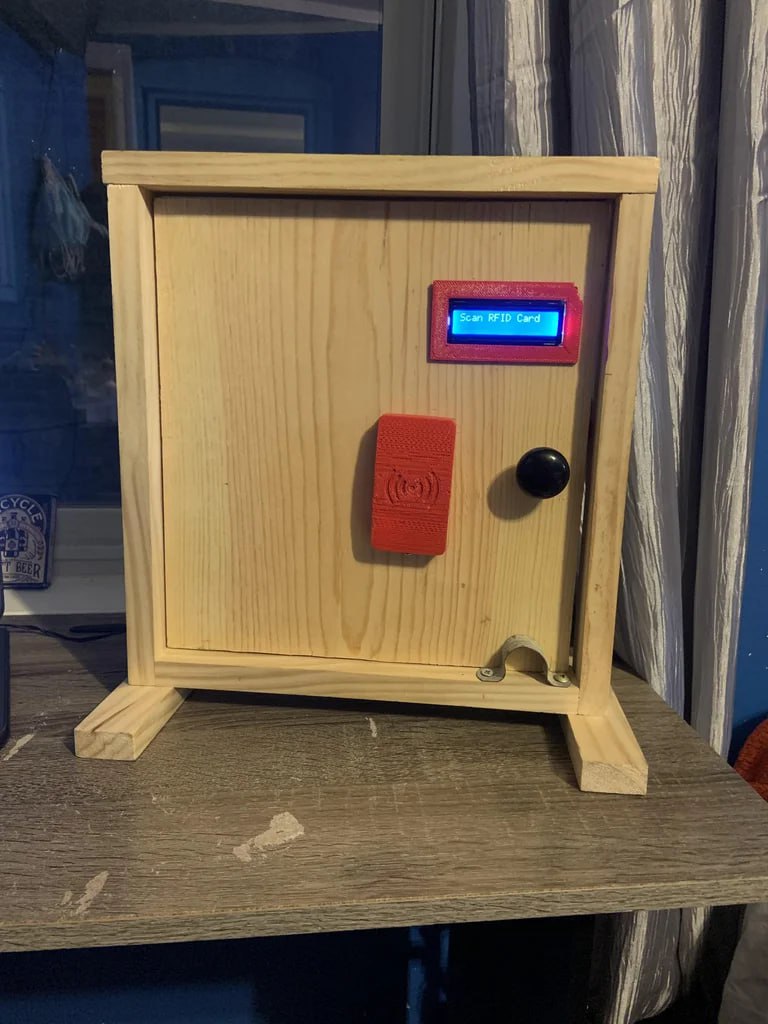
How the RFID Smart Door Lock Works
The RFID Smart Door Lock System is an electronic security system that uses an Arduino Uno and an RFID reader to control access to a door. Instead of using a traditional key, the user simply places an authorized RFID card near the reader.
When the RFID card is detected, the RC522 RFID reader reads the card's unique identification number (UID) and sends it to the Arduino. The Arduino then compares the UID with the authorized cards stored in its program.
🔑 Access Granted
If the scanned card matches one of the four authorized RFID cards:
The LCD displays “Access Granted.”
The green LED turns on.
The buzzer produces a short confirmation sound.
The servo motor rotates to 90°, unlocking the door.
After approximately 5 seconds, the servo returns to its locked position.
The system returns to “Scan Your Card.”
🚫 Access Denied
If an unauthorized card is scanned:
The LCD displays “Access Denied.”
The red LED turns on.
The buzzer produces a longer warning sound.
The servo remains in the locked position.
After a short delay, the system is ready for another card.
⚙️ Main Components
The project combines several components to create the complete system:
Arduino Uno — controls the entire system.
RC522 RFID Reader — reads RFID cards.
Servo Motor — physically locks and unlocks the door.
16×2 I2C LCD — displays system messages.
Green LED — indicates authorized access.
Red LED — indicates denied access.
Buzzer — provides audio feedback.
RFID Cards — act as electronic access keys.
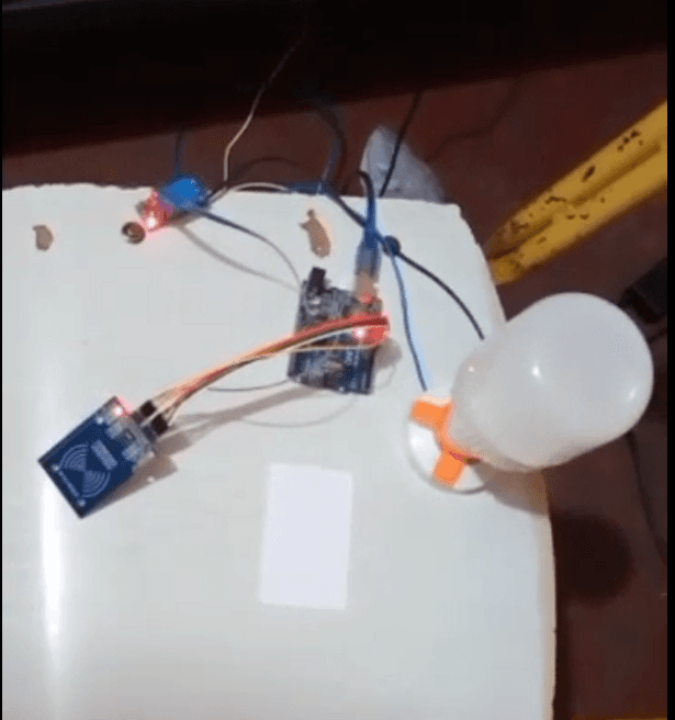
Components and Their Functions
The RFID Smart Door Lock System is made up of several electronic components that work together to provide automatic access control.
🔧 1. Arduino Uno
The Arduino Uno is the main controller of the project. It receives information from the RFID reader, checks whether the scanned card is authorized, and controls the servo motor, LEDs, buzzer, and LCD.
📡 2. RC522 RFID Reader
The RC522 RFID reader detects and reads the unique ID (UID) of an RFID card. This UID is sent to the Arduino for verification.
🪪 3. RFID Cards
The RFID cards act as the electronic keys for the system. Four authorized card UIDs are stored in the Arduino program. Only recognized cards can unlock the door.
🚪 4. Servo Motor
The servo motor controls the physical locking mechanism. It rotates to 90° to unlock the door and returns to 0° to lock it again.
📺 5. 16×2 I2C LCD
The LCD provides information to the user. It displays messages such as:
RFID Door Lock
Scan Your Card
Access Granted
Access Denied
🟢 6. Green LED
The green LED indicates that an authorized card has been detected and access has been granted.
🔴 7. Red LED
The red LED indicates that an unauthorized card has been detected and access has been denied.
🔊 8. Buzzer
The buzzer provides audio feedback. It produces a short sound for successful access and a longer warning sound when an unauthorized card is scanned.
🔌 9. Jumper Wires and Breadboard
Jumper wires are used to connect the components, while the breadboard makes it easier to build and test the circuit without soldering.
🔗 How Everything Works Together
RFID Card → RC522 Reader → Arduino Uno → Verification → LCD + LED + Buzzer + Servo